Modelling Geothermal Doublets
A geothermal doublet consist of a production and injection well, which at reservoir level are spaced around is a software tool developed by TNO which calculates how much water can be pumped at a given pump power, given a doublet system and subsurface conditions. It is based on a simple subsurface model and standardised well design (Figure 1). The DoubletCalc1D calculation method is the basis of the ThermoGIS calculation model described here. The software and manual can be downloaded from Doubletcalc1D.
The premises for the calculation of the geothermal energy, given the aquifer, wells and heat exchanger characteristics are:
-
Mass balance: the mass flow (kg/s) is constant in the doublet system from the intake in the production well until the injection in the aquifer.
-
Impulse balance (pressure balance): this is valid for the entire doublet system and for all of the elements within the system. The sum of the pressure differences over all element in the system is zero. The pressure balance determines the mass flow at a given pump pressure.
-
Energy balance: this is valid for all elements within the system. Release of heat to the immediate surroundings of the well and temperature drop in the heat exchanger are taken into account.
Figure 1 is a schematic representation of the doublet system. The numbered nodes, are used to describe the components of the pressure and energy balances. Further details of the model can be found in the manual of DoubletCalc1D
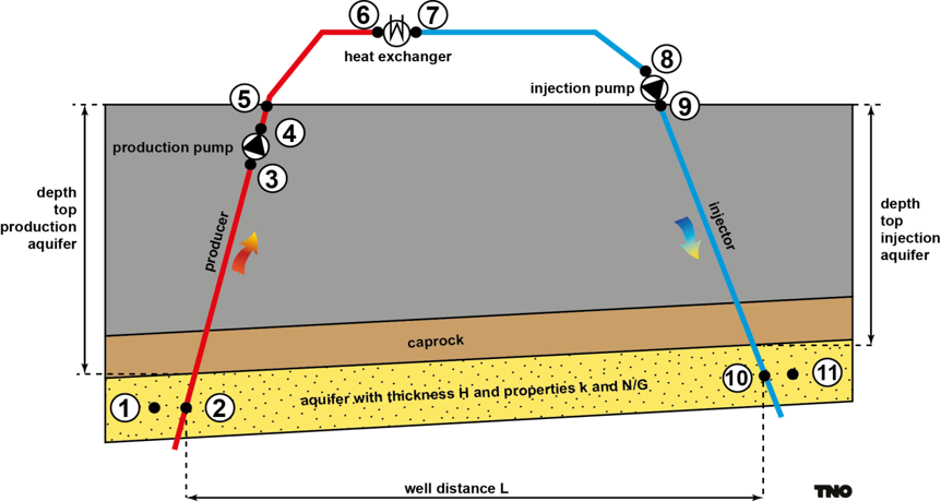
Figure 1: Figure of a doublet system, showing the production well and injection well, with the reservoir in between. The production well extracts hot water from the reservoir, which is then used to produce energy, while the injection well returns cooled water back into the reservoir.
The following parameter values are proposed for the doublet model, which can be adjusted in the ThermoGIS configuration file. The Skin factor of -1 corresponds to having a 45° slanted well in the reservoir and the -3 corresponds to the situation after well stimulation (hydraulic or acidication) or drilling horizontal or multilateral sections in the reservoir.
The applied pressure to drive production and injection includes the following aspects:
- hydrological resistance of the reservoir
- frictional resistance in the wellbores
- thermosyphon effects in the producer and injector well
The maximum allowed pressure is typically limited to ca 30% of the hydrostatic pressure at the reservoir depth, and can be set via various parameters including maximum injection pressure.
The well distance is optimized in such a way that the maximum cooling of the production water is 1% of ΔT after 50 years. This means that the difference between production water and return (injection) temperature after 50 years, is at least 99% of the original temperature difference.
| Technical parameter | symbol | value | unit |
|---|---|---|---|
| use Kestin visicosty | kestin_use | True | bool |
| distance between the two wells at reservoir | L | optimized | m |
| pump system efficiency | ESPn | 0.6 | - |
| production pump depth | ESPz | 500 | m |
| pump pressure, limited to 30% of hydrostatic pressure | ΔPtotal | optimized | bar |
| well trajectory curvature factor | scurve | 1.1 | - |
| calculation segment length | Δz | 50 | m |
| inner diameter (casing) | dw | 8.5 | inch |
| casing roughness | m | 1.38 | milli-inch |
| injector well skin (with stimulation) | Sinj | -1 (-3) | - |
| production well skin (with stimulation) | Sprod | -1 (-3) | - |